

-
General Purpose Valve Series Butterfly valve series Ball valve series Hydraulic control valve series Corrosion-resistant valve series Bellows valve series Regulating valve seriesThree eccentric butterfly valve series Two-way double eccentric metal hard seal butterfly valve Soft seal butterfly valve series Other Butterfly Valve SeriesHydraulic control valve series Multi-function water control valve Elastic Seated Gate Valve On-off electric valve


- All
- Product Management
- News
- Introduction
- Enterprise outlets
- FAQ
- Enterprise Video
- Enterprise Atlas

Share:
Cast steel forged steel ball valve
If you are interested in our products, Please contact us
Product classification
Key words:
Product Details
Cast steel forged steel ball valve
CLASS150Lb、300Lb、400Lb、600Lb、900Lb、1500Lb、2500Lb PN16、25、40、64、100、160、250、420 bar NPS1/2"~32"
Forged steel fixed ball valve is developed by Simac technicians using the latest international technical standards. It is mainly used for long-distance pipeline transportation of oil and natural gas and city gas pipeline system. Due to the unique characteristics of long-distance pipeline valves, the ability to withstand pipeline stress, as well as safety, weather resistance, and long-term reliability are fully considered in the design; sealing and structural design are unique to Simac. The operation mode includes manual-scroll turbine drive, pneumatic, electric, gas/liquid linkage, electric/liquid linkage, and various special control forms.
Main Functional Features
- Truncation and emission
- Secure Decompression
- Reliable sealing
- Fire Safety
- Cleaning the pipeline
- Emergency sealing
- Special valve seat
- Bonnet combination seal
- Blowdown
- Lend reading pole
- Standby class driving mode
- Various connection modes
- Valve body material variety
- Valve seat material variety
- Various control systems
- Reliable operation
- Withstand pipeline stress safety
Structural features
1. Forged steel structure
The valve body is made of forged steel, which can ensure sufficient strength and rigidity under the maximum rated working pressure, without the inherent defects of the casting. Valve internal parts are carefully designed and selected to ensure reliability under various operating conditions. Split body wall thickness and the use of high-strength connecting bolts, is conducive to the maintenance and maintenance of the valve, and enough to withstand the stress of the pipeline.
2. Low operating torque
The ball is a fixed ball, and the spherical surface is ground, polished and hardened by the envelope grinding ball process, and is separated from the valve stem; the valve stem is a slender shaft with a hardened surface; the axial load of the ball is passed on to the valve body by two large self-lubricating dynamic bearings, so it is resistant to wear and has flexible operation and low torque.
Name of main parts
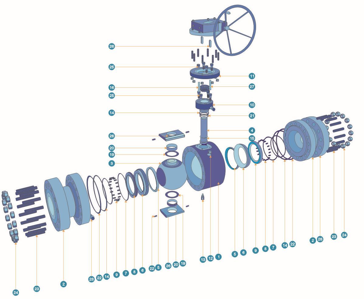
| 01. Valve body | 15. Retaining ring |
| 02. Side valve body | 16. Filler |
| 03. Sphere | 17. Fireproof sealing gasket |
| 04. Stem | 18. Fireproof sealing gasket |
| 05. Seat | 19. Thrust bearing |
| 06. Valve seat support | 20. Bearings |
| 07. Fire washer | 21. Bearing pedestal |
| 08. Spring seat | 22. Pin |
| 09. Spring | 23. Studs |
| 10. stuffing box | 24. Hexagon nut |
| 11. Coupling disc | 25. Hexagon socket head cap screw |
| 12. Blow valve | 26. Key |
| 13. Blow valve | 27. Locating pin |
| 14.0 ring | 28. grease injection valve |
3. Advanced sphere fixing method
The ball is fixed on the valve body through two bearing seats symmetrical up and down, and the valve body bears the axial load of the ball. Therefore, the valve stem separated from the ball does not bear bending load, realizing pure torque operation. At the same time, the axial load of the ball is closer to the center, the acting force radius is reduced, and the bearing seat is close to the outer diameter of the pipeline, so the stress condition is improved, the service life is longer, and the sealing is more reliable.
4. Reliable sealing
Valve seal is made of soft sealing material and metal bearing ring components to complete; seat seal is made of rubber soft seal and metal combination seal structure, especially suitable for containing dust natural gas and sand crude oil harsh conditions. The seat support ring is axially floating, through the spring preloading to achieve low-pressure sealing of the valve seat, and reasonable design of the piston effect of the valve seat, relying on the pressure of the medium itself to achieve high-pressure sealing, so as to achieve the purpose of cutting off the medium. At the same time, the design of fire seal ring to achieve the fire state of the seal.
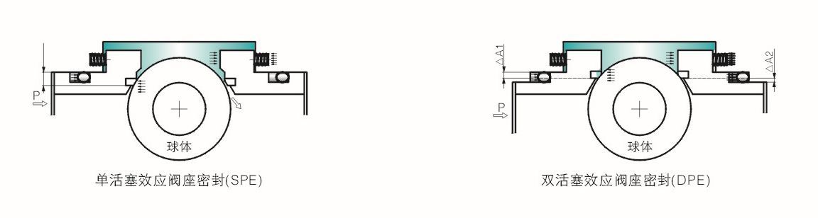
5. Principle of Seat Piston Effect
The sealing principle of the ball valve (non-forced sealing) is to rely on the pressure of the medium itself to achieve sealing, and the method used is usually to use the principle of piston effect. The valve seat sealing structure is divided into single-piston effect and double-piston effect. When the upstream and downstream valve seats are both single-piston effect and double-piston effect, the ball valve seals the upstream and downstream valve seats at the same time, the sealing reliability is greatly improved, but if it is used for liquid media, an automatic pressure relief valve must be installed on the valve body, and a single piston upstream (upstream self-pressure relief) and a double piston sealing structure downstream can be adopted. At this time, the valve has the requirements of installation direction.
6. Emergency Sealing
The valve stem/gland part and the side valve seat support part are designed with grease injection holes, and grease injection valves are installed. If the valve stem and/or valve seat seal is damaged and causes leakage, sealing grease can be used to achieve secondary sealing. Each grease injection valve is equipped with a built-in check valve to prevent the leakage of sealing grease under the action of the medium. The end of the grease injection valve is a connector for quick connection of the grease injection gun.
7. Double Truncation and Bleeder (DBB)
When the ball is in the fully open or fully closed position, the cavity medium in the valve body can be discharged through the drainage and venting device. At the same time, the overpressure of the valve cavity can be discharged to the low pressure end by the self-discharging valve seat.
8. Vlow device
NPT vent hole is processed in the upper part of the valve body. The vent hole is installed with a vent valve after the pressure test of the valve body. The cavity in the valve body can be vented and cleaned during valve operation.
9. Fire Protection Design
The valve design meets the requirements of API 6FA/API 607 standards, and has passed the fire test, and the test proves that it meets the requirements.
10. Anti-static design
Static electricity generated by friction between metal and plastic or rubber is very dangerous for transporting flammable and explosive media. Therefore, for the electrical conductivity between metal parts (such as valve body, ball, seat support ring, valve stem) isolated by plastic or rubber seals, stainless steel springs are used to ensure compliance with BS5351.
11. Material selection
The materials of the valve parts shall meet the requirements of API6D, ASTM, ANSI and other specifications. The surface treatment of the parts shall be carried out in different ways according to the working conditions. The requirements for sulfide stress corrosion resistance shall be carried out according to the requirements of NACE MR 0175.
12. Lender valve stem
For direct-mounted valves, the valve stem can be extended and the corresponding grease injection blowdown can be extended to the top of the valve for easy operation.
13. Diverse modes of operation
The connecting plate of the valve and the driver shall comply with the provisions of the IS05211, which is convenient for the connection and exchange of all kinds of drivers. Common driving modes include manual, electric, pneumatic, gas-liquid linkage, etc.
| Part Name | Materials | ||||||
|---|---|---|---|---|---|---|---|
| Standard ST. Carbon Steel | Internal A182-F6 | 304 of internal parts | 316 of internal parts | Internal EIMP | NACE MR 01-75)① | Low temperature series (-46 ℃)② | |
| Valve body | ASTM A105 | ASTM A105 | ASTM A105 | ASTM A105 | ASTM A105 | ASTM A105 | ASTM A350(G)LF2 |
| Side valve body | ASTM S105 | ASTM A105 | ASTM A105 | ASTM A105 | ASTM A105 | ASTM A105 | ASTM A350(G)LF2 |
| Sphere | ASTM A105.ENP | ASTM A182-F6a | 304SS ENP | 316SS ENP | ASTM A105 ENP | ASTM A105 HCr | ASTMA350(G)LF2 HCr |
| Stem | ASTMA276-410 HCr | ASTM A276-410 HQ | 304SS HCr | 316SS HCr | ASTM A276-410 ENP | ASTM A276-410 HCr | ASTTM A276-410 HCr |
| Valve seat | PTFE/NYLON/PEEK | PTFE/NYLON/PEEK | PTFE/NYLON/PEEK | PTFE/NYLON/PEEK | PTFE/NYLON/PEEK | PTFE/NYLON/PEEK | FTFE/NYLON/PEEK |
| Valve seat support | ASTM A105 ENP | ASTM A182-F6a | 304SS ENP | 316SS ENP | ASTN A105 ENP | ASTN A105 Zn | ASTM A350(G)LF2 Zn |
| seat pressure ring | ASTM A105 ENP | ASTM A182-F6a | 304SS -f ENP | 316SS ENP | ASTN A105 ENP | ASTN A105 Zn | ASTM A350(G)LF2 Zn |
| Valve seat snap ring | 304 SS | 304 SS | 304 SS | 316 SS | 304 SS | 304 SS | 304 SS |
| Spring | INCONEL X-750 | INCONEL X-750 | INCONEL X-750 | INCONEL X-750 | INCONEL X-750 | INCONEL X-750 | INCONEL X-750 |
| gland | ASTM A105 | ASTM A105 | ASTM A105 | ASTM A105 | ASTM A105 | ASTM A105 | ASTM A350(G)LF2 |
| Coupling disc | ASTM A105 | ASTM A105 | ASTM A105 | ASTM A105 | ASTM A105 | ASTM A105 | ASTM A350(G)LF2 |
| Vent valve | ASTM A105 | ASTM A105 | 304 SS | 316 SS | ASTM A105 | ASTM A105 | ASTM A350(G)LF2 |
| Blow valve | ASTM A105 | ASTM A105 | 304 SS | 316 SS | ASTM A105 | ASTM A105 | ASTM A350(G)LF2 |
| 0 type seal | VITON | VITON | VITON | VITON | VITON | VITON | VITON |
| Retaining ring | VITON | VITON | VITON | VITON | VITON | VITON | VITON |
| Packing | expanded graphite | expanded graphite | expanded graphite | expanded graphite | expanded graphite | expanded graphite | expanded graphite |
| Fireproof sealing gasket | metal-wound graphite | metal-wound graphite | metal-wound graphite | metal-wound graphite | metal-wound graphite | metal-wound graphite | metal-wound graphite |
| Fireproof sealing gasket | metal-wound graphite | metal-wound graphite | metal-wound graphite | metal-wound graphite | metal-wound graphite | metal-wound graphite | metal-wound graphite |
| Thrust bearing | PTFE | PTFE | PTFE | PTFE | PTFE | PTFE | PTFE |
| Bearing seat | ASTM A105 | ASTM A105 | ASTM A105 | ASTM A105 | ASTM A105 | ASTM A105 | ASTM A350(G)LF2 |
| Pin | AISI 4140 | AISI 4140 | AISI 4140 | AISI 4140 | AISI 4140 | AISI 4140 | AISI 4140 |
| Double-headed inspection | ASTM A193-B7 | ASTM A193-B7 | ASTM A193-B7 | ASTM A193-B7M | ASTM A193-B7M | ASTM A193-B7M | ASTM A320(G)L7.Zn |
| Hexagon nut | ASTM A194-2H | ASTM A194-2H | ASTM A194-2H | ASTM A194-2HM | ASTM A194-2HM | ASTM A194-2HM | ASTM A194-7 • Zn |
| cylinder head screw | ASTM A193-B7 | ASTM A193-B7 | ASTM A193-B7 | ASTM A193-B7M | ASTM A193-B7M | ASTM A193-B7M | ASTM A320(G)L7.Zn |
| Seat abdication screw set | ASTM A193-B7 | ASTM A193-B7 | ASTM A193-B7 | ASTM A193-B7M | ASTM A193-B7M | ASTM A193-B7M | ASTM A320(G)L7.Zn |
| Key | ASTM A194-2H | ASTM A194-2H | ASTM A194-2H | ASTM A194-2HM | ASTM A194-2HM | ASTM A194-2HM | ASTM A194-7 • Zn |
| Locating Pin | AISI 4140 | AISI 4140 | AISI 4140 | AISI 4140 | AISI 4140 | AISI 4140 | AISI 4140 |
| grease injection valve | Components | Components | Components | Components | Components | Components | Components |
| Anti-static miscellaneous | Components | Components | Components | Components | Components | Components | Components |
| tripod | ASTM A105 | ASTM A105 | ASTM A105 | ASTM A105 | ASTM A105 | ASTM A105 | ASTM A105 |
| Lifting lugs | ASTM A105 | ASTM A105 | ASTM A105 | ASTM A105 | ASTM A105 | ASTM A105 | ASTM A105 |
| Check Valve | Components | Components | Components | Components | Components | Components | Components |
| Safety valve | Components | Components | Components | Components | Components | Components | Components |
| Fireproof seal ring | expanded graphite | expanded graphite | expanded graphite | expanded graphite | expanded graphite | expanded graphite | expanded graphite |
Note:
① NACE state, spring hardness ≤ HRC28, hardness of other materials ≤ HRC22;
② T≤ 30 ℃. M rod needs to be lengthened (but the valve stem does not need to be lengthened under low ambient temperature)
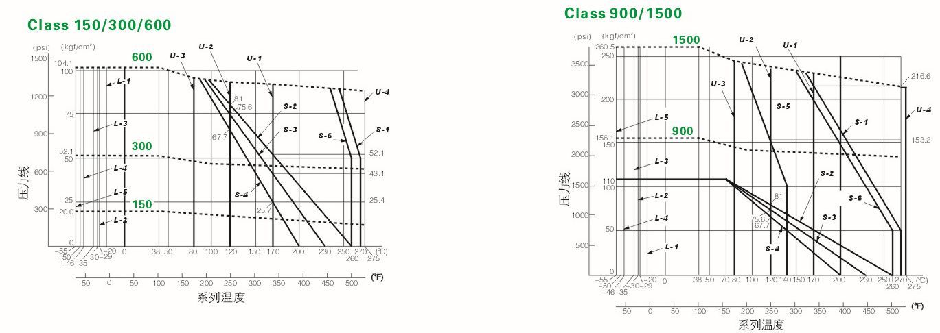
Valve body • Valve seat • O-ring
The use of soft sealing ball valve temperature, pressure rating depends not only on the body material, but also depends on the sealing material, such as valve seat, O-ring, stem packing.
Temperature-Pressure Rating
The following table lists the temperature and pressure ratings of the main body materials. It is in accordance with the American standard ASME/ANSI B16.34.
| Temperature | Maximum working pressure | ||||||||||||
|---|---|---|---|---|---|---|---|---|---|---|---|---|---|
| 150Lb | 300Lb | 400Lb | 600Lb | 900Lb | 1500Lb | ||||||||
| OF | °C | A105.LF2 | ASTM A182F316 | A105.LF2 | ASTM A182F316 | A105.LF2 | ASTM A182 F316 | A105.LF2 | ASTM A182F316 | A105.LF2 | ASTM A182F316 | A105.LF2 | ASTM A182F316 |
| UP to | UP to | Bar | Bar | Bar | Bar | Bar | Bar | Bar | Bar | Bar | Bar | Bar | Bar |
| 100 | 38 | 19.7 | 19 | 51 | 49.6 | 68.3 | 66.2 | 102 | 99.3 | 153.1 | 148.9 | 255.5 | 248.2 |
| 200 | 93 | 17.9 | 16.5 | 46.5 | 42.7 | 62.1 | 56.9 | 93.1 | 85.5 | 139.6 | 128.2 | 232.7 | 213.4 |
| 300 | 149 | 15.9 | 14.8 | 45.2 | 38.6 | 60.3 | 51.4 | 90.7 | 77.2 | 135.8 | 115.8 | .226.1 | 192.7 |
| 400 | 204 | 13.8 | 13.4 | 43.8 | 35.5 | 58.3 | 47.2 | 87.6 | 71.0 | 131.0 | 106.2 | 218.6 | 177.2 |
| 500 | 264 | 11.7 | 11.7 | 41.4 | 33.1 | 55.2 | 43.8 | 82.7 | 65.8 | 123.8 | 98.9 | 206.5 | 164.8 |
Seat • O-Ring Temperature-Pressure Rating
Seat Category
S-1 PEEK
S-2 carbon fiber PTFE
S-3
S-4 Virgin PTFE
S-5 Nylon MoS2
S-6 PPL
Upper temperature limit of O-ring
U-1:(1)FPM (stainless steel valve)
(2) Low temperature FPM
U-2:(1)EPDM (2)EC0
U-3: (1)NBR (2) Low temperature NBR
U-4: Kalrez(6375)
Lower temperature limit of O-ring
L-1 FPM (for stainless steel valves)
L-2 (1)EPDM(2) NBR
L-3 low temperature FPM
L-4 ECO
L-5 low temperature NBR
| Type Q47F, 0F7F * Q347F, 0WF7F * | |||||||||||||
|---|---|---|---|---|---|---|---|---|---|---|---|---|---|
| Path | L RF |
L RTJ |
L BW |
W1 | H1 | H2 | E | F | Φw | Type | Weight | ||
| DN | INCH | Code | (Kg) | ||||||||||
| 15 | 1/2" | 108 | 119 | 140 | 145 | For of | 65 | For of | F | | |||
| 20x15 | 3/4"x1/2" | 117 | 130 | 152 | 145 | For of | 68 | For of | For of | For of | F | For of | |
| 20 | 3/4" | 117 | 130 | 152 | 145 | For of | 73 | For of | For of | For of | F | For of | |
| 25x20 | 1"x3/4" | 127 | 140 | 165 | 145 | For of | 76 | For of | For of | For of | F | For of | |
| 25 | 1" | 127 | 140 | 165 | 165 | For of | 96 | For of | For of | For of | F | For of | |
| 32x25 | 1 ¼ "x1" | 140 | 153 | 178 | 165 | For of | 105 | For of | For of | For of | F | For of | |
| 32 | 1 ¼" | 140 | 153 | 178 | 165 | For of | 120 | For of | For of | For of | F | For of | |
| 40x32 | 1 ½" | 165 | 178 | 191 | 165 | For of | 130 | For of | For of | For of | F | For of | |
| 40 | 1 ½" | 165 | 178 | 190 | 230 | 70 | 135 | For of | For of | For of | F | 12 | |
| 50x40 | 2 "x 1 ½" | 178 | 191 | 216 | 230 | 70 | 135 | For of | For of | For of | F | 15 | |
| 50 | 2" | 178 | 191 | 216 | 230 | 80 | 150 | For of | For of | For of | F | 16 | |
| 80x50 | 3"x2" | 203 | 216 | 283 | 230 | 80 | 150 | For of | For of | For of | F/G | 32 | |
| 80 | 3" | 203 | 216 | 283 | 400 | 100 | 200 | For of | For of | For of | F/G | 36 | |
| 100x80 | 4"x3" | 229 | 241 | 305 | 400 | 100 | 200 | For of | For of | For of | F/G | 53 | |
| 100 | 4" | 229 | 241 | 305 | 650 | 115 | 240 | For of | For of | For of | F/G | 70 | |
| 150x100 | 6"x4" | 394 | 406 | 457 | 650 | 115 | 240 | For of | For of | For of | F/G | 94 | |
| 150 | 6" | 394 | 406 | 457 | For of | 260 | 340 | 85 | 180 | 450 | F/G | 145 | |
| 200x150 | 8"x6" | 457 | 470 | 521 | For of | 260 | 340 | 85 | 180 | 450 | F/G | 260 | |
| 200 | 8" | 457 | 470 | 521 | For of | 300 | 389 | 116 | 350 | 600 | F/G | 346 | |
| 250x200 | 10"x8" | 533 | 546 | 559 | For of | 300 | 389 | 116 | 350 | 600 | F/G | 375 | |
| 250 | 10" | 533 | 546 | 559 | For of | 325 | 405 | 116 | 350 | 600 | G | 540 | |
| 300x250 | 12"x10" | 610 | 622 | 635 | For of | 325 | 405 | 116 | 350 | 600 | G | 675 | |
| 300 | 12" | 610 | 622 | 635 | For of | 365 | 455 | 171 | 420 | 800 | G | 850 | |
| 350x300 | 14"x12" | 686 | 699 | 762 | For of | 365 | 455 | 171 | 420 | 800 | G | 890 | |
| 350 | 14" | 686 | 699 | 762 | For of | 400 | 490 | 171 | 800 | G | 1060 | ||
| 400x300 | 16"x12" | 762 | 775 | 838 | For of | 365 | 455 | 171 | 420 | 800 | G | 1200 | |
| 400x350 | 16"x14" | 762 | 775 | 838 | For of | 400 | 490 | 171 | 420 | 800 | G | 1300 | |
| 400 | 16" | 762 | 775 | 838 | For of | 440 | 550 | 257 | 400 | 800 | G | 1380 | |
| 450x350 | 18"x14" | 864 | 876 | 914 | For of | 400 | 490 | 171 | 400 | 800 | G | 1400 | |
| 450x400 | 18"x16" | 864 | 876 | 914 | For of | 440 | 550 | 257 | 400 | 800 | G | 1455 | |
| 450 | 18" | 864 | 876 | 914 | For of | 500 | 620 | 257 | 400 | 800 | G | 1910 | |
| 500x400 | 20"x16" | 914 | 927 | 991 | For of | 440 | 550 | 257 | 400 | 800 | G | 1810 | |
| 500x450 | 20"x18" | 914 | 927 | 991 | For of | 500 | 620 | 257 | 400 | 800 | G | 2130 | |
| 500 | 20" | 914 | 927 | 991 | For of | 555 | 680 | 257 | 400 | 800 | G | 2300 | |
| 550x450 | 22"x18" | 1016 | For of | 1092 | For of | 500 | 620 | 257 | 400 | 800 | G | 2315 | |
| 550x500 | 22"x20" | 1016 | For of | 1092 | For of | 555 | 680 | 257 | 400 | 800 | G | 2400 | |
| 550 | 22" | 1016 | For of | 1092 | For of | 635 | 806 | 150 | 410 | 800 | G | 2435 | |
| 600x500 | 24"x20" | 1067 | 1080 | 1143 | - | 555 | 680 | 257 | 400 | 800 | G | 2450 | |
| 600x550 | 24"x22" | 1067 | 1080 | 1143 | - | 635 | 806 | 150 | 410 | 800 | G | 2750 | |
| 600 | 24" | 1067 | 1080 | 1143 | - | 700 | 870 | 150 | 410 | 800 | G | 3180 | |
| 700x600 | 28"24" | 1245 | - | 1346 | - | 700 | 870 | 150 | 410 | 800 | G | 3610 | |
| 700 | 28" | 1245 | - | 1346 | - | 780 | 955 | 183 | 650 | 800 | G | 4480 | |
| Type Q47F, OF7F * Q347F, OWF7F * | |||||||||||||
|---|---|---|---|---|---|---|---|---|---|---|---|---|---|
| Path | L RF |
L RTJ |
L BW |
W1 | H1 | H2 | E | F | Φw | Type | Weight | ||
| DN | INCH | Code | (Kg) | ||||||||||
| 15 | 1/2" | 140 | 151 | 140 | 145 | 70 | F | 6 | |||||
| 20x15 | 3/4"x1/2" | 152 | 165 | 152 | 145 | — | 75 | — | — | — | F | 7 | |
| 20 | 3/4" | 152 | 165 | 152 | 145 | — | 80 | — | — | — | F | 8 | |
| 25x20 | 1 ¼ "x¾" | 165 | 178 | 165 | 145 | — | 85 | — | — | — | F | 9 | |
| 25 | 1" | 165 | 178 | 165 | 165 | — | 100 | — | — | — | F | 10 | |
| 32x25 | 1 ¼ x 1" | 178 | 191 | 178 | 165 | — | 105 | — | — | — | F | 11 | |
| 32 | 1 ¼" | 178 | 191 | 178 | 165 | — | 126 | — | — | — | F | 13 | |
| 40x32 | 1½"x1¼" | 190 | 203 | 190 | 165 | — | 135 | — | — | — | F | 14 | |
| 40 | 1 ½" | 190 | 203 | 190 | 230 | 70 | 135 | — | — | — | F | 15 | |
| 50x40 | 2 "x 1 ½" | 216 | 232 | 216 | 230 | 70 | 135 | — | — | — | F | 18 | |
| 50 | 2" | 216 | 232 | 216 | 230 | 80 | 150 | — | — | — | F/G | 33 | |
| 80x50 | 3"x2" | 283 | 299 | 283 | 230 | 80 | 150 | — | — | — | F/G | 36 | |
| 80 | 3" | 283 | 299 | 283 | 400 | 100 | 200 | — | — | — | F/G | 41 | |
| 100x80 | 4"x3" | 305 | 321 | 305 | 400 | 100 | 200 | — | — | — | F/G | 53 | |
| 100 | 4" | 305 | 321 | 305 | 650 | 115 | 240 | — | — | — | F/G | 81 | |
| 150x100 | 6"x4" | 403 | 419 | 403 | 650 | 115 | 240 | — | — | — | F/G | 105 | |
| 150 | 6" | 403 | 419 | 403 | — | 260 | 340 | 85 | 180 | 450 | F/G | 155 | |
| 200x150 | 8"x6" | 502 | 518 | 521 | — | 260 | 340 | 85 | 180 | 450 | F/G | 285 | |
| 200 | 8" | 502 | 518 | 521 | — | 300 | 389 | 116 | 350 | 600 | G | 360 | |
| 250x200 | 10"x8" | 568 | 584 | 559 | — | 300 | 389 | 116 | 350 | 600 | G | 390 | |
| 250 | 10" | 568 | 584 | 559 | — | 325 | 405 | 116 | 350 | 600 | G | 585 | |
| 300x250 | 12"x10" | 648 | 664 | 635 | — | 325 | 405 | 116 | 350 | 600 | G | 720 | |
| 300 | 12" | 648 | 664 | 635 | — | 365 | 455 | 171 | 420 | 800 | G | 890 | |
| 350x300 | 14"x12" | 762 | 778 | 762 | — | 365 | 455 | 171 | 420 | 800 | G | 905 | |
| 350 | 14" | 762 | 778 | 762 | — | 400 | 490 | 171 | 420 | 800 | G | 1160 | |
| 400x300 | 16"x12" | 838 | 854 | 838 | — | 365 | 455 | 171 | 420 | 800 | G | 1280 | |
| 400x350 | 16"x14" | 838 | 854 | 838 | — | 400 | 490 | 171 | 420 | 800 | G | 1350 | |
| 400 | 16" | 838 | 854 | 838 | — | 440 | 550 | 257 | 400 | 800 | G | 1560 | |
| 450x350 | 18"x14" | 914 | 930 | 914 | — | 400 | 490 | 171 | 400 | 800 | G | 1500 | |
| 450x400 | 18"x16" | 914 | 930 | 914 | — | 440 | 550 | 257 | 400 | 800 | G | 1730 | |
| 450 | 18" | 914 | 930 | 914 | — | 500 | 620 | 257 | 400 | 800 | G | 2420 | |
| 500x400 | 20"x16" | 991 | 1010 | 991 | — | 440 | 550 | 257 | 400 | 800 | G | 2010 | |
| 500x450 | 20"X18" | 991 | 1010 | 991 | — | 500 | 620 | 257 | 400 | 800 | G | 2505 | |
| 500 | 20" | 991 | 1010 | 991 | — | 555 | 680 | 257 | 400 | 800 | G | 2610 | |
| 550x450 | 22"x18" | 1092 | 1114 | 1092 | — | 500 | 620 | 257 | 400 | 800 | G | 2630 | |
| 550x500 | 22"x20" | 1092 | 1114 | 1092 | — | 555 | 680 | 257 | 400 | 800 | G | 2670 | |
| 550 | 22" | 1092 | 1114 | 1092 | — | 635 | 806 | 150 | 410 | 800 | G | 2700 | |
| 600x500 | 24"x20" | 1143 | 1165 | 1143 | — | 555 | 680 | 257 | 400 | 800 | G | 2950 | |
| 600x550 | 24"x22" | 1143 | 1165 | 1143 | — | 635 | 806 | 150 | 410 | 800 | G | 3200 | |
| 600 | 24" | 1143 | 1165 | 1143 | — | 700 | 870 | 150 | 410 | 800 | G | 5025 | |
| 700x600 | 28"x24" | 1346 | 1372 | 1346 | — | 700 | 870 | 150 | 410 | 800 | G | 4310 | |
| 700 | 28" | 1346 | 1372 | 1346 | — | 780 | 955 | 83 | 650 | 800 | G | 5170 | |
| Q47F\0F7F * Q347Fs0WF7F * type | |||||||||||||
|---|---|---|---|---|---|---|---|---|---|---|---|---|---|
| Path | L RF |
L RTJ |
L BW |
W1 | H1 | H2 | E | F | Φw | Type | Weight | ||
| DN | INCH | Code | (Kg) | ||||||||||
| 15 | 1/2" | 165 | 163 | 165 | 160 | — | 102 | — | — | — | F | 6 | |
| 20 | 3/4" | 190 | 190 | 190 | 160 | — | 115 | — | — | — | F | 9 | |
| 25 | 1" | 216 | 216 | 216 | 230 | — | 125 | — | — | — | F | 11 | |
| 40 | 1 ½" | 241 | 241 | 241 | 400 | — | 140 | — | — | — | F | 22 | |
| 50x40 | 2 "x 1 ½" | 292 | 295 | 292 | 400 | — | 140 | — | — | — | F | 23 | |
| 50 | 2" | 292 | 295 | 292 | 400 | 93 | 190 | — | — | — | F/G | 39 | |
| 80x50 | 3"x2" | 356 | 359 | 356 | 650 | 93 | 190 | — | — | — | F/G | 46 | |
| 80 | 3" | 356 | 359 | 356 | 650 | 122 | 230 | — | — | — | F/G | 83 | |
| 100x80 | 4"x3" | 406 | 410 | 406 | — | 122 | 230 | — | — | — | F/G | 96 | |
| 100 | 4" | 406 | 410 | 406 | — | 152 | 280 | 85 | 180 | 450 | F/G | 120 | |
| 150x100 | 6"x4" | 495 | 498 | 495 | — | 152 | 280 | 85 | 180 | 450 | F/G | 192 | |
| 150 | 6" | 495 | 498 | 495 | — | 215 | 327 | 116 | 350 | 600 | F/G | 301 | |
| 200x150 | 8"x6" | 597 | 600 | 597 | — | 215 | 327 | 116 | 350 | 600 | F/G | 360 | |
| 200 | 8" | 597 | 600 | 597 | — | 294 | 374 | 171 | 420 | 800 | G | 520 | |
| 250x200 | 10"x8" | 673 | 676 | 673 | — | 294 | 374 | 171 | 420 | 800 | G | 630 | |
| 250 | 10" | 673 | 676 | 673 | — | 370 | 445 | 171 | 420 | 800 | G | 760 | |
| 300x250 | 12"x10" | 762 | 765 | 762 | — | 370 | 445 | 171 | 420 | 800 | G | 880 | |
| 300 | 12" | 762 | 765 | 762 | — | 420 | 515 | 257 | 400 | 800 | G | 1360 | |
| 350x300 | 14"x12" | 826 | 829 | 826 | — | 420 | 515 | 257 | 400 | 800 | G | 1480 | |
| 350 | 14" | 826 | 829 | 826 | — | 460 | 550 | 257 | 400 | 800 | G | 1620 | |
| 400x300 | 16"x12" | 902 | 905 | 902 | — | 420 | 515 | 257 | 400 | 800 | G | 1700 | |
| 400x350 | 16"x14" | 902 | 905 | 902 | — | 460 | 550 | 257 | 400 | 800 | G | 1780 | |
| 400 | 16" | 902 | 905 | 902 | — | 505 | 615 | 257 | 400 | 800 | G | 1860 | |
| 450x350 | 18"x14" | 978 | 981 | 978 | — | 460 | 550 | 257 | 400 | 800 | G | 1848 | |
| 450x400 | 18"x16" | 978 | 981 | 978 | — | 505 | 615 | 257 | 400 | 800 | G | 2080 | |
| 450 | 18" | 978 | 981 | 978 | — | 560 | 700 | 150 | 410 | 800 | G | 2336 | |
| 500x400 | 20"x16" | 1054 | 1060 | 1054 | — | 505 | 615 | 257 | 400 | 800 | G | 2230 | |
| 500x450 | 20"x18" | 1054 | 1060 | 1054 | — | 560 | 700 | 150 | 410 | 800 | G | 2450 | |
| 500 | 20" | 1054 | 1060 | 1054 | — | 630 | 810 | 150 | 410 | 800 | G | 2900 | |
| 550x450 | 22"x18" | 1143 | 1153 | 1143 | — | 560 | 700 | 150 | 410 | 800 | G | 2950 | |
| 550x500 | 22"x20" | 1143 | 1153 | 1143 | — | 630 | 810 | 150 | 410 | 800 | G | 3060 | |
| 550 | 22" | 1143 | 1153 | 1143 | — | 660 | 830 | 180 | 565 | 800 | G | 3340 | |
| 600x500 | 24"x20" | 1232 | 1241 | 1232 | — | 630 | 810 | 150 | 410 | 800 | G | 3130 | |
| 600x550 | 24"x22" | 1232 | 1241 | 1232 | — | 660 | 830 | 180 | 565 | 800 | G | 3485 | |
| 600 | 24" | 1232 | 1241 | 1232 | — | 685 | 845 | 180 | 565 | 800 | G | 3825 | |
| 700x600 | 28"x24" | 1397 | 1410 | 1397 | — | 685 | 845 | 180 | 565 | 800 | G | 6190 | |
| 700 | 28" | 1397 | 1410 | 1397 | — | 810 | 1010 | 200 | 800 | 800 | G | 7030 | |
| Type Q47F, OF7F * Q347F, OWF7F * | |||||||||||||
|---|---|---|---|---|---|---|---|---|---|---|---|---|---|
| Path | L RF |
L RTJ |
L BW |
W1 | H1 | H2 | E | F | Φw | Type | Weight | ||
| DN | INCH | Code | (Kg) | ||||||||||
| 15 | 1/2" | 165 | 163 | 165 | 160 | — | 102 | — | — | — | F | 6 | |
| 20 | 3/4" | 190 | 190 | 190 | 160 | — | 102 | — | — | — | F | 9 | |
| 25 | 1" | 216 | 216 | 216 | 230 | — | 115 | — | — | — | F | 11 | |
| 40 | 1 ½" | 241 | 241 | 241 | 400 | — | 125 | — | — | — | F | 22 | |
| 50x40 | 2 "x 1 ½" | 292 | 295 | 292 | 400 | — | 140 | — | — | — | F/G | 23 | |
| 50 | 2" | 292 | 295 | 292 | 400 | 93 | 140 | — | — | — | F/G | 39 | |
| 80x50 | 3"x2" | 356 | 359 | 356 | 400 | 93 | 190 | — | — | — | F | 46 | |
| 80 | 3" | 356 | 359 | 356 | 650 | 122 | 190 | — | — | — | F | 83 | |
| 100x80 | 4"x3" | 432 | 435 | 432 | 650 | 122 | 230 | — | — | — | F | 120 | |
| 100 | 4" | 432 | 435 | 432 | — | 152 | 230 | 85 | 180 | 450 | F/G | 150 | |
| 150x100 | 6"x4" | 559 | 562 | 559 | — | 152 | 280 | 85 | 180 | 450 | G | 240 | |
| 150 | 6" | 559 | 562 | 559 | — | 215 | 280 | 116 | 350 | 600 | G | 377 | |
| 200x150 | 8"x6" | 660 | 664 | 660 | — | 215 | 327 | 116 | 350 | 600 | G | 450 | |
| 200 | 8" | 660 | 664 | 660 | — | 294 | 327 | 171 | 420 | 800 | G | 650 | |
| 250x200 | 10"x8" | 787 | 791 | 787 | — | 294 | 374 | 171 | 420 | 800 | G | 780 | |
| 250 | 10" | 787 | 791 | 787 | — | 370 | 374 | 171 | 420 | 800 | G | 950 | |
| 300x250 | 12"x10" | 838 | 841 | 838 | — | 370 | 445 | 171 | 420 | 800 | G | 1100 | |
| 300 | 12" | 838 | 841 | 838 | — | 420 | 445 | 257 | 400 | 800 | G | 1700 | |
| 350x300 | 14"x12" | 889 | 892 | 889 | — | 420 | 515 | 257 | 400 | 800 | G | 1850 | |
| 350 | 14" | 889 | 892 | 889 | — | 460 | 515 | 257 | 400 | 800 | G | 2050 | |
| 400x300 | 16"x12" | 991 | 994 | 991 | — | 420 | 550 | 257 | 400 | 800 | G | 2150 | |
| 400x350 | 16"x14" | 991 | 994 | 991 | — | 460 | 550 | 257 | 400 | 800 | G | 2200 | |
| 400 | 16" | 991 | 994 | 991 | — | 505 | 615 | 257 | 400 | 800 | G | 2325 | |
| 450x350 | 18"x14" | 1092 | 1095 | 1092 | — | 460 | 550 | 257 | 400 | 800 | G | 2310 | |
| 450x400 | 18"x16" | 1092 | 1095 | 1092 | — | 505 | 615 | 257 | 400 | 800 | G | 2600 | |
| 450 | 18" | 1092 | 1095 | 1092 | — | 560 | 700 | 150 | 410 | 800 | G | 2920 | |
| 500x400 | 20"x16" | 1194 | 1200 | 1194 | — | 505 | 615 | 257 | 400 | 800 | G | 2850 | |
| 500x450 | 20"x18" | 1194 | 1200 | 1194 | — | 560 | 700 | 150 | 410 | 800 | G | 3120 | |
| 500 | 20" | 1194 | 1200 | 1194 | — | 630 | 810 | 150 | 410 | 800 | G | 3400 | |
| 550x450 | 22"x18" | 1295 | 1305 | 1295 | — | 560 | 700 | 150 | 410 | 800 | G | 3450 | |
| 550x500 | 22"x20" | 1295 | 1305 | 1295 | — | 630 | 810 | 150 | 410 | 800 | G | 3600 | |
| 550 | 22" | 1295 | 1305 | 1295 | — | 660 | 920 | 83 | 650 | 800 | G | 3930 | |
| 600x500 | 24"x20" | 1397 | 1407 | 1397 | — | 630 | 810 | 150 | 410 | 800 | G | 3980 | |
| 600x550 | 24"x22" | 1397 | 1407 | 1397 | — | 660 | 920 | 83 | 650 | 800 | G | 4100 | |
| 600 | 24" | 1397 | 1407 | 1397 | — | 685 | 1010 | 83 | 650 | 800 | G | 4500 | |
| 700x600 | 28"x24" | 1549 | 1562 | 1549 | — | 685 | 1010 | 83 | 650 | 800 | G | 7280 | |
| 700 | 28" | 1549 | 1562 | 1549 | — | 810 | 1180 | 123 | 800 | 800 | G | 8280 | |
| Type Q47F, 0F7F * Q347F, 0WF7F * | |||||||||||||
|---|---|---|---|---|---|---|---|---|---|---|---|---|---|
| Path | L RF |
L RTJ |
L BW |
W1 | H1 | H2 | E | F | Φw | Type | Weight | ||
| DN | INCH | Code | (Kg) | ||||||||||
| 15 | 1/2" | 216 | 216 | 216 | 175 | — | 117 | — | — | — | F | ||
| 20 | 3/4" | 229 | 229 | 229 | 280 | — | 140 | — | — | — | F | ||
| 25 | 1" | 255 | 255 | 255 | 280 | — | 150 | — | — | — | F | ||
| 40 | 1 ½" | 305 | 305 | 305 | 400 | 119 | 210 | — | — | — | F | ||
| 50x40 | 2 "x 1 ½" | 368 | 371 | 368 | 400 | 119 | 210 | — | — | — | F/G | ||
| 50 | 2" | 368 | 371 | 368 | 650 | 126 | 217 | — | — | — | F/G | ||
| 80x50 | 3"x2" | 381 | 384 | 381 | 650 | 126 | 217 | — | — | — | F/G | ||
| 80 | 3" | 381 | 384 | 381 | — | 191 | 259 | 116 | 350 | 600 | F/G | ||
| 100x80 | 4"x3" | 457 | 460 | 457 | — | 191 | 259 | 116 | 350 | 600 | F/G | ||
| 100 | 4" | 457 | 460 | 457 | — | 216 | 297 | 116 | 350 | 600 | F/G | ||
| 150x100 | 6"x4" | 610 | 613 | 610 | — | 216 | 297 | 116 | 350 | 600 | G | ||
| 150 | 6" | 610 | 613 | 610 | — | 270 | 360 | 116 | 350 | 600 | G | ||
| 200x150 | 8"x6" | 737 | 740 | 737 | — | 270 | 360 | 116 | 350 | 600 | G | ||
| 200 | 8" | 737 | 740 | 737 | — | 322 | 394 | 171 | 420 | 800 | G | ||
| 250x200 | 10"x8" | 838 | 841 | 838 | — | 322 | 394 | 171 | 420 | 800 | G | ||
| 250 | 10" | 838 | 841 | 838 | — | 420 | 502 | 257 | 400 | 800 | G | ||
| 300x250 | 12"x10" | 965 | 968 | 965 | — | 420 | 502 | 257 | 400 | 800 | G | ||
| 300 | 12" | 965 | 968 | 965 | — | 470 | 572 | 257 | 400 | 800 | G | ||
| 350x300 | 14"x12" | 1029 | 1038 | 1029 | — | 470 | 572 | 257 | 400 | 800 | G | ||
| 350 | 14" | 1029 | 1038 | 1029 | — | 510 | 675 | 150 | 410 | 800 | G | ||
| 400x300 | 16"x12" | 1130 | 1140 | 1130 | — | 470 | 572 | 257 | 400 | 800 | G | ||
| 400x350 | 16"x14* | 1130 | 1140 | 1130 | — | 510 | 675 | 150 | 410 | 800 | G | ||
| 400 | 16" | 1130 | 1140 | 1130 | — | 600 | 762 | 150 | 410 | 800 | G | ||
| 450x350 | 18"x14" | 1219 | 1232 | 1219 | — | 510 | 675 | 150 | 410 | 800 | G | ||
| 450x400 | 18"x16" | 1219 | 1232 | 1219 | — | 600 | 762 | 150 | 410 | 800 | G | ||
| 450 | 18" | 1219 | 1232 | 1219 | — | 700 | 866 | 180 | 650 | 800 | G | ||
| 500x400 | 20"x16" | 1321 | 1334 | 1321 | — | 600 | 762 | 150 | 410 | 800 | G | ||
| 500x450 | 20"x18" | 1321 | 1334 | 1321 | — | 700 | 866 | 180 | 650 | 800 | G | ||
| 500 | 20" | 1321 | 1334 | 1321 | — | 720 | 894 | 180 | 650 | 800 | G | ||
| 600x500 | 24"x20" | 1549 | 1568 | 1549 | — | 720 | 894 | 180 | 650 | 800 | G | ||
| 600x550 | 24"x22" | 1549 | 1568 | 1549 | — | 765 | 925 | 220 | 735 | 800 | G | ||
| 600 | 24" | 1549 | 1568 | 1549 | — | 810 | 956 | 220 | 735 | 800 | G | ||
| Type Q47F, OF7F * Q347F, OWF7F * | |||||||||||||
|---|---|---|---|---|---|---|---|---|---|---|---|---|---|
| Path | L RF |
L RTJ |
L BW |
W1 | H1 | H2 | E | F | Φw | Type | Weight | ||
| DN | INCH | Code | (Kg) | ||||||||||
| 15 | 1/2" | 216 | 216 | 216 | 175 | — | 117 | — | — | — | F | ||
| 20 | 3/4" | 229 | 229 | 229 | 280 | — | 140 | — | — | — | F | ||
| 25 | 1" | 255 | 255 | 255 | 280 | — | 150 | — | — | — | F | ||
| 40 | 1 ½" | 305 | 305 | 305 | 400 | 119 | 210 | — | — | — | F/G | ||
| 50x40 | 2 "x 1 ½" | 368 | 371 | 368 | 400 | 119 | 210 | — | — | — | F/G | ||
| 50 | 2" | 368 | 371 | 368 | 650 | 126 | 217 | — | — | — | F/G | ||
| 80x50 | 3"x2" | 470 | 473 | 470 | 650 | 126 | 217 | — | — | — | G | ||
| 80 | 3" | 470 | 473 | 470 | — | 191 | 259 | 116 | 350 | 600 | G | ||
| 100x80 | 4"x3" | 546 | 549 | 546 | — | 191 | 259 | 116 | 350 | 600 | G | ||
| 100 | 4" | 546 | 549 | 546 | — | 216 | 297 | 116 | 350 | 600 | G | ||
| 150x100 | 6"x4" | 705 | 711 | 705 | — | 216 | 297 | 116 | 350 | 600 | G | ||
| 150 | 6" | 705 | 711 | 705 | — | 296 | 365 | 171 | 420 | 800 | G | ||
| 200x150 | 8"x6" | 832 | 841 | 832 | — | 296 | 365 | 171 | 420 | 800 | G | ||
| 200 | 8" | 832 | 841 | 832 | — | 378 | 475 | 257 | 400 | 800 | G | ||
| 250x200 | 10"x8" | 991 | 1000 | 991 | — | 378 | 475 | 257 | 400 | 800 | G | ||
| 250 | 10" | 991 | 1000 | 991 | — | 495 | 578 | 257 | 400 | 800 | G | ||
| 300x250 | 12"x10" | 1130 | 1146 | 1130 | — | 495 | 578 | 257 | 400 | 800 | G | ||
| 300 | 12" | 1130 | 1146 | 1130 | — | 542 | 696 | 150 | 410 | 800 | G | ||
| 350x300 | 14"x12" | 1257 | 1276 | 1257 | — | 542 | 696 | 150 | 410 | 800 | G | ||
| 350 | 14" | 1257 | 1276 | 1257 | — | 590 | 761 | 150 | 410 | 800 | G | ||
| 400x300 | 16"x12" | 1384 | 1407 | 1384 | — | 542 | 696 | 150 | 410 | 800 | G | ||
| 400x350 | 16"x14" | 1384 | 1407 | 1384 | — | 590 | 761 | 150 | 410 | 800 | G | ||
| 400 | 16" | 1384 | 1407 | 1384 | — | 670 | 831 | 180 | 650 | 800 | G | ||
| 450x350 | 18"x14" | 1537 | 1559 | 1537 | — | 590 | 761 | 150 | 410 | 800 | G | ||
| 450x400 | 18"x16" | 1537 | 1559 | 1537 | — | 670 | 831 | 180 | 650 | 800 | G | ||
| 450 | 18" | 1537 | 1559 | 1537 | — | 710 | 900 | 220 | 735 | 800 | G | ||
| 500x400 | 20x16" | 1664 | 1686 | 1664 | — | 670 | 831 | 180 | 650 | 800 | G | ||
| 500x450 | 20"x18" | 1664 | 1686 | 1664 | — | 710 | 900 | 220 | 735 | 800 | G | ||
| 500 | 20" | 1664 | 1686 | 1664 | — | 750 | 950 | 220 | 735 | 800 | G | ||
| 600x500 | 24"x20" | 2043 | 2071 | 2043 | — | 750 | 950 | 220 | 735 | 800 | G | ||
| 600x550 | 24"x22" | 2043 | 2071 | 2043 | — | 800 | 1015 | 280 | 1010 | 800 | G | ||
| 600 | 24" | 2043 | 2071 | 2043 | — | 850 | 1080 | 280 | 1010 | 800 | G | ||
| Type Q47F, OF7F * Q347F, OWF7F * | |||||||||||||
|---|---|---|---|---|---|---|---|---|---|---|---|---|---|
| Path | L RF |
L RTJ |
L BW |
W1 | H1 | H2 | E | F | Φw | Type | Weight | ||
| DN | INCH | Code | (Kg) | ||||||||||
| 15 | 1/2" | 264 | 264 | 264 | 280 | — | 120 | — | — | — | F | ||
| 20 | 3/4" | 273 | 273 | 273 | 280 | — | 125 | — | — | — | F | ||
| 25 | 1" | 308 | 308 | 308 | 400 | — | 130 | — | — | — | F/G | ||
| 40 | 1 ½" | 384 | 387 | 384 | 650 | 135 | 188 | — | — | — | F/G | ||
| 50x40 | 2 "x 1 ½" | 451 | 454 | 451 | 650 | 135 | 188 | — | — | — | F/G | ||
| 50 | 2" | 451 | 454 | 451 | — | 135 | 262 | 85 | 240 | 600 | G | ||
| 80x50 | 3"x2" | 578 | 584 | 578 | — | 135 | 262 | 85 | 240 | 600 | G | ||
| 80 | 3" | 578 | 584 | 578 | — | 181 | 256 | 116 | 350 | 600 | G | ||
| 100x80 | 4"x3" | 673 | 683 | 673 | — | 181 | 256 | 116 | 350 | 600 | G | ||
| 100 | 4" | 673 | 683 | 673 | — | 225 | 287 | 171 | 420 | 800 | G | ||
| 150x100 | 6"x4" | 914 | 927 | 914 | — | 225 | 287 | 171 | 420 | 800 | G | ||
| 150 | 6" | 914 | 927 | 914 | — | 287 | 372 | 257 | 400 | 800 | G | ||
| 200x150 | 8"x6" | 1022 | 1038 | 1022 | — | 287 | 372 | 257 | 400 | 800 | G | ||
| 200 | 8" | 1022 | 1038 | 1022 | — | 350 | 411 | 257 | 400 | 800 | G | ||
| 250x200 | 10"x8" | 1292 | 1293 | 1270 | — | 350 | 411 | 257 | 400 | 800 | G | ||
| PN | 150Lb(2.0MPa) | 300Lb(5.0MPa) | 400Lb(6.4MPa) | 600Lb(10.0MPa) | 900Lb(16.0MPa) | 1500Lb(25.0MPa) | 2500Lb(42.0MPa) | ||||||||
|---|---|---|---|---|---|---|---|---|---|---|---|---|---|---|---|
| Torque | Torque INI • m | Torque INI • m | Torque INI • m | Torque INI • m | Torque INI • m | Torque INI • m | Torque INI • m | ||||||||
| NPS | Valve opening torque | Valve stem tolerance torque | Valve opening torque | Valve stem tolerance torque | Valve opening torque | Valve stem tolerance torque | Valve opening torque | Valve stem tolerance torque | Valve opening torque | Valve stem tolerance torque | Valve opening torque | Valve stem tolerance torque | Valve opening torque | Valve stem tolerance torque | |
| Under full differential pressure | Under full differential pressure | Under full differential pressure | Under full differential pressure | Under full differential pressure | Under full differential pressure | Under full differential pressure | |||||||||
| 1" | — | — | — | — | — | 40 | 130 | 44 | 130 | 90 | 270 | 190 | 570 | — | — |
| 1-½" | 2 "x 1-½" | 30 | 180 | 60 | 180 | 50 | 225 | 75 | 225 | 120 | 360 | 230 | 690 | — | — |
| 2n | 3"x2" | 42 | 225 | 75 | 225 | 97 | 345 | 115 | 345 | 240 | 720 | 400 | 1200 | 950 | 2850 |
| 2 ½" | — | 100 | 450 | 150 | 450 | 160 | 660 | 220 | 660 | 380 | 1140 | 640 | 1920 | 1200 | 3600 |
| 3" | 4"x3" | 140 | 630 | 210 | 630 | 200 | 840 | 280 | 840 | 480 | 1440 | 800 | 2400 | 1580 | 4740 |
| 4" | 6"x4" | 220 | 1080 | 360 | 1080 | 360 | 1380 | 460 | 1380 | 800 | 2400 | 1450 | 4350 | 2300 | 6900 |
| 6" | 8"x6" | 320 | 2040 | 480 | 1440 | 640 | 2850 | 950 | 2850 | 1600 | 4800 | 2800 | 8400 | 5500 | 16500 |
| 8n | 10"x8" | 640 | 2550 | 850 | 2550 | 1200 | 4800 | 1600 | 4800 | 2800 | 8400 | 4000 | 12000 | 11800 | 35400 |
| 10" | 12"x10" | 1200 | 4350 | 1450 | 4350 | 2000 | 8100 | 2700 | 8100 | 4800 | 14400 | 8000 | 24000 | — | — |
| 12" | 14"x12" | 1800 | 6900 | 2300 | 6900 | 3200 | 12900 | 4300 | 12900 | 7200 | 21600 | 12800 | 38400 | — | — |
| 14" | 16"x14" | 2600 | 9900 | 3300 | 9900 | 4500 | 18600 | 6200 | 18600 | 11000 | 33000 | 18500 | 55500 | — | — |
| 16" | 18nx16" | 3800 | 14400 | 4800 | 14400 | 6400 | 26400 | 8800 | 26400 | 14400 | 43200 | 26500 | 79500 | — | — |
| 18" | 20"x18" | 4800 | 19200 | 6400 | 19200 | 8800 | 36000 | 12000 | 36000 | 19200 | 57600 | 36000 | 108000 | — | — |
| 20" | 24"x20" | 6400 | 24000 | 8000 | 24000 | 11000 | 42000 | 14000 | 42000 | 27200 | 81600 | 48000 | 144000 | — | — |
| 22" | 24"x22" | 8000 | 28200 | 9400 | 28200 | 14000 | 60000 | 60000 | 60000 | 32000 | 96000 | 60000 | 180000 | — | — |
| 24" | 28"x24" | 10000 | 36000 | 12000 | 36000 | 16000 | 66000 | 66000 | 66000 | 40000 | 120000 | 74500 | 223500 | — | — |
| 26" | — | — | — | — | — | — | — | — | — | — | — | — | — | — | — |
| 28" | — | 14000 | 52500 | 17500 | 52500 | 23000 | 90000 | 30000 | 90000 | 48000 | 144000 | 89500 | 268500 | — | — |
- Nominal torque of driving device = valve full differential pressure opening torque X 1.3 times safety factor.
- The above data are measured for clean gas or liquid media. The data changes if the media is not clean.
Get Quote
Related Products

")


National sales hotline 7*24 hours
Address: 801-805 Jingshan Road, Guannan Industrial Zone, jimei district, Xiamen City


