Bellows valve is a kind of valve with bellows as sealing element, with high temperature resistance, high pressure resistance, corrosion resistance and other characteristics, widely used in petrochemical, electric power, metallurgy, nuclear energy and other fields, is an important representative of high-performance valves.
(Enterprise Standard) Q/DFL 12 - 99 Company standard
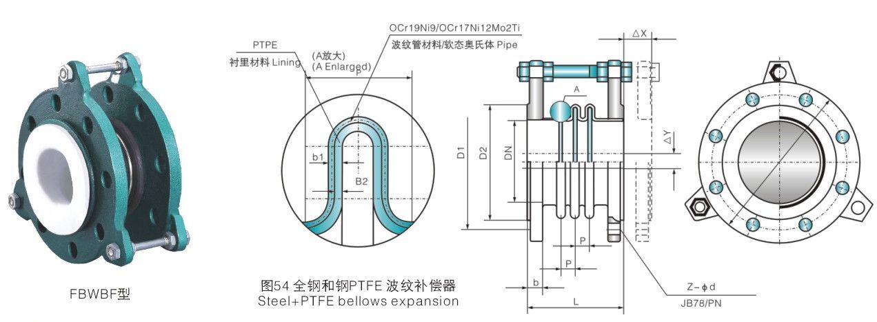
Face to face length
(Enterprise Standard) Q/DFL 13-99 Company standard
Flange size Flange dimension
JB78 (or as required by the contract) Or according to contract
Pressure Test
GB/T 13927
Main connection dimensions and weight Dimensions and weights
表(Table)B54
Nominal diameter Size DN(mm)
Model Type
wave number wave n
Design Length L0(mm)
Axial lining is Axial amunt AX(mm)
Radial compensation is Ridial amount AY(mm)
Angle amount A 0 (mm)
Nominal pressure Pressure PN(MPa)
25
FXZ25 x 3
3
78
±15
8
25
0.6
FXZ25 x 4
4
96
±20
10
28
0.6
FXZ25 x 5
5
114
±25
12
30
0.6
FXZ25 x 6
6
132
±30
12
32
0.6
32
FXZ32 x 3
3
78
±15
8
25
0.6
FXZ32 x 4
4
96
±20
10
28
0.6
FXZ32 x 5
5
114
±25
11
30
0.6
FXZ32 x 6
6
132
±30
12
32
0.6
40
FXZ40 x 3
3
92
±18
8
25
0.6
FXZ40 x 4
4
113
±25
10
28
0.6
FXZ40 x 5
5
134
±23
11
30
0.6
FXZ40 x 6
6
155
±40
12
32
0.6
50
FXZ50 x 3
3
98
±18
10
25
0.6
FXZ50 x 4
4
122
±25
14
28
0.6
FXZ50 x 5
5
145
±33
16
30
0.6
FXZ50 x 6
6
170
±40
18
32
0.6
65
FXZ65 x 3
3
105
±20
16
25
0.6
FXZ65 x 4
4
131
±27
21
28
0.6
FXZ65 x 5
5
154
±34
23
30
0.6
FXZ65 x 6
6
183
±41
25
32
0.6
80
FXZ80 x 3
3
110
±20
16
25
0.6
FXZ80 x 4
4
137
±27
21
28
0.6
FXZ80 x 5
5
164
±34
23
30
0.6
FXZ80 x 6
6
191
±41
25
32
0.6
100
FXZ100x3
3
115
±25
16
22
0.6
FXZ100x4
4
143
±32
21
28
0.6
FXZ100x5
5
171
±39
23
30
0.6
FXZ100x6
6
199
±46
5
32
0.6
125
FXZ125x3
3
123
±27
15
19
0.6
FXZ125x4
4
154
±34
21
24
0.6
FXZ125x5
5
185
±41
24
26
0.6
FXZ125x6
6
216
±48
28
28
0.6
150
FXZ150x3
3
123
±27
12
16
0.4
FXZ150x4
4
155
±34
20
20
0.4
FXZ150x5
5
187
±41
24
24
0.4
FXZ150x6
6
219
±48
26
26
0.4
200
FXZ200x3
3
150
±27
12
14
0.4
FXZ200x4
4
188
±34
20
18
0.4
FXZ200x5
5
226
±41
24
20
0.4
FXZ200x6
6
264
±48
26
22
0.4
250
FXZ250x3
3
160
±27
9
11
0.25
FXZ250x4
4
200
±34
16
14
0.25
FXZ250x5
5
240
±41
18
15
0.25
FXZ250x6
6
280
±48
20
18
0.25
* The allowable service pressure of the compensator-decreases as the caliber increases.
Main connection dimensions/Dimensions
表(Table)B 54
Nominal diameter Size DN(mm)
Model Type
wave number wave n
Design Length L0(mm)
Axial lining compensation Axial amunt△X (mm)
Radial compensation amount Ridial amount △Y(mm)
Angle amount △θ (mm)
Nominal pressure Pressure PN(MPa)
300
FXZ300x3
3
180
±27
8
9
0.25
FXZ300x4
4
228
±34
14
12
0.25
FXZ300x5
5
276
±41
16
14
0.25
FXZ300x6
6
324
±48
18
16
0.25
350
FXZ350x3
3
188
±27
7
8
0.25
FXZ350x4
4
238
±34
12
10
0.25
FXZ350x5
5
288
±41
15
12
0.25
FXZ350x6
6
338
±48
16
14
0.25
400
FXZ400x3
3
230
±30
6
7
0.15
FXZ400x4
4
270
±35
10
9
0.15
FXZ400x5
5
280
±42
15
10
0.15
FXZ400x6
6
325
±49
16
12
0.15
450
FXZ450x3
3
230
±30
5
6
0.15
FXZ450x4
4
270
±35
9
8
0.15
FXZ450x5
5
290
±42
12
9
0.15
FXZ450x6
6
340
±49
14
10
0.15
500
FXZ500x3
3
230
±30
5
6
0.15
FXZ500x4
4
270
±35
9
8
0.15
FXZ500x5
5
290
±42
11
9
0.15
FXZ500x6
6
340
±49
13
10
0.15
1000
FXZ1000
1
250
±20
10
2.2
0.10
1200
FXZ1200
1
250
±20
10
1.9
0.10
1400
FXZ1400
1
250
±20
10
1.6
0.08
1500
FXZ1500
1
280
±20
10
1.5
0.08
1600
FXZ1600
1
280
±20
10
1.4
0.05
1800
FXZ1800
1
280
±20
10
1.2
0.05
2000
FXZ2000
1
300
±20
10
1.1
0.03
2200
FXZ2200
1
300
±20
10
1.0
0.03
2400
FXZ2400
1
300
±20
15
0.9
0.03
2600
FXZ2600
1
300
±20
15
0.8
0.03
2800
FXZ2800
1
300
±20
15
0.8
0.03
3000
FXZ3000
1
300
±20
15
0.7
0.01
3200
FXZ3200
1
300
±20
15
0.7
0.01
3400
FXZ3400
1
300
±20
15
0.6
0.01
3600
FXZ3600
1
300
±20
20
0.6
0.01
3800
FXZ3800
1
300
±20
20
0.6
0.01
4000
FXZ4000
1
300
±20
20
0.5
0.01
4200
FXZ4200
1
300
±20
20
0.5
0.01
4400
FXZ4400
1
300
±20
20
0.5
0.01
4600
FXZ4600
1
300
±20
20
0.4
0.01
4800
FXZ4800
1
300
±20
20
0.4
0.01
5000
FXZ5000
1
300
±20
20
0.4
0.01
5400
FXZ5400
1
300
±20
20
0.4
0.01
5800
FXZ5800
1
300
±20
20
0.3
0.01
6000
FXZ6000
1
300
±20
20
0.3
0.01
* The allowable service pressure of the compensator-decreases as the caliber increases.
Main connection dimensions/Dimensions
表(Table)B56
Nominal diameter Size(DN)
Length(L)
Axial compression Axial compressing
Axial tensile Axial extending
Lateral displacement Hoizontal movment
Deflection angle Deflection angle
32
95
8
4
8
15°
40
95
8
5
8
15°
50
105
8
5
8
15°
65
115
12
6
10
15°
80
135
12
6
10
15°
100
150
18
10
12
15°
125
165
18
10
12
15°
150
180
18
10
12
15°
200
190
25
14
15
15°
250
230
25
14
15
15°
300
245
25
14
15
15°
350
255
25
15
15
15°
400
255
25
15
15
12°
450
255
25
15
22
12°
500
255
25
16
22
12°
600
260
25
16
22
12°
700
320
25
16
22
12°
800
340
25
16
22
12°
900
370
25
16
22
10°
1000
400
25
16
22
10°
1200
420
26
18
24
10°
1400
450
28
20
26
10°
1600
500
35
25
30
10°
1800
500
35
25
30
10°
2000
550
35
25
30
10°
* The allowable service pressure of the compensator-decreases as the caliber increases.
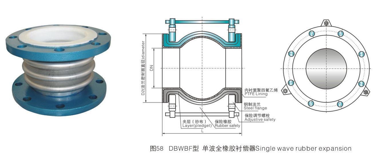
Basic Parameters/Basic Parameter
※ nominal pressure Pressure: PN0.6 ~ 1.6(MPa) ※ nominal diameter Size: DN32 ~ 2000(mm) ※ wave number Wave: 1 wave Wave all-rubber single-wave compensator 1. This piece can greatly reduce the vibration and noise of the pipeline system, and can fundamentally solve the problems of interface displacement, extension and non-concentricity of the spare pipeline. 2. According to different materials, it can be made into various varieties such as acid resistance, alkali resistance, corrosion resistance, oil resistance, heat resistance, etc., to adapt to a variety of media and environments. 3. The material is polar rubber, with good sealing, light weight, convenient installation and maintenance, and long service life, but avoid contact with sharp metal instruments to avoid piercing the sphere. 4. If the elastic bracket can be equipped for overhead use, the bolts shall be tightened diagonally during installation. 5. If the pipeline pressure is too high, the flanges at both ends shall be connected together with limit bolts. 6, flange connection standard GB4216.3 ~ 4216.5 standard can also be selected according to customer requirements HG, JB, ANSI or DIN standard.
Our website uses cookies and similar technologies to personalize the advertising shown to you and to help you get the best experience on our website. For more information, see our Privacy & Cookie Policy
COOKIES
Our website uses cookies and similar technologies to personalize the advertising shown to you and to help you get the best experience on our website. For more information, see our Privacy & Cookie Policy
These cookies are necessary for basic functions such as payment. Standard cookies cannot be turned off and do not store any of your information.
These cookies collect information, such as how many people are using our site or which pages are popular, to help us improve the customer experience. Turning these cookies off will mean we can't collect information to improve your experience.
These cookies enable the website to provide enhanced functionality and personalization. They may be set by us or by third-party providers whose services we have added to our pages. If you do not allow these cookies, some or all of these services may not function properly.
These cookies help us understand what you are interested in so that we can show you relevant advertising on other websites. Turning these cookies off will mean we are unable to show you any personalized advertising.


 ※ nominal pressure Pressure: PN0.01 ~ 0.25(MPa)
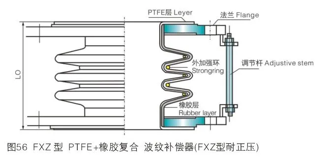
")


